As EV Battery Density Increases, Why Thermal Interface Materials Are Becoming the Bottleneck
Ten years ago, the thermal interface material in a battery module was an afterthought. Today, it’s a first-order design decision. Here’s how we got here — and where it’s going.
The POV
Thermal interface materials are no longer a commodity procurement decision for EV battery packs. They are a materials engineering decision that affects thermal performance, reliability, and end-of-life value in ways that the commodity approach underprices — and that must be made concurrently with cell chemistry, module architecture, and cooling system design.
From Afterthought to First-Order Design Decision
The shift in TIM importance didn’t happen because engineers changed their philosophy. It happened because the physics changed — and the old assumptions no longer hold at next-generation energy densities.
The Density Equation — Why the Math Forces the Issue
Current-generation cylindrical cells (4680 format) and next-generation prismatic cells target energy densities 30–50% higher than the cells they replace. Higher energy density means more heat generated per unit volume — and the thermal path from cell surface to cooling plate has to carry it.
A gap pad that performed adequately in a first-generation pack may add 5–10°C of thermal resistance in a next-generation pack running at higher power density. That 5–10°C translates directly to a narrower thermal operating window, faster cell degradation at pack edges, and a more expensive battery management system trying to compensate for what the TIM should have addressed.
The Heat Removal Problem
The thermal management system has to remove heat faster as energy density increases. Active liquid cooling is becoming standard — but the bottleneck isn’t the cooling system. It’s the thermal path from cell surface to cooling plate
The TIM Is in the Middle
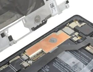
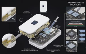
The thermal interface material sits exactly in the middle of the critical heat removal path — between where heat is generated (cell surface) and where it’s removed (cooling plate)
The TC Escalation
A material at 4 W/mK adequate at 10 W/cm² becomes a design constraint at 25 W/cm². The thermal budget doesn’t expand with power density — the TIM TC has to. The escalation is physics, not marketing
Cell Degradation at Pack Edges
Non-uniform thermal resistance across a pack creates temperature gradients — cells at higher-resistance interfaces degrade faster, shortening pack lifetime and complicating cell balancing
Why Liquid Gap Filler Is Replacing Gap Pads in New Pack Designs
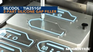
The shift toward liquid dispensed gap fillers in EV battery modules is driven by three specific requirements of next-generation pack design that gap pads handle poorly — not by preference, but by physics and geometry.
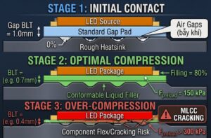
Thinner Bondlines — Gap Pads Can’t Reliably Achieve <500 µm
High-density packs need thermal interfaces at 80–150 µm BLT, not 500 µm–1 mm. Gap pads cannot reliably achieve this without generating unacceptable compression stress on the cell casing. Liquid gap fillers achieve 80 µm BLT at 10–50 psi — controlled by assembly closure geometry, not pad thickness.
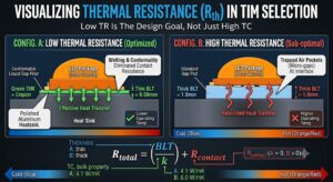
At 80 µm BLT and 4.1 W/mK, TR = 30 mm²K/W (Laser Flash measured). At 1 mm gap pad BLT and 6 W/mK, TR = 167 mm²K/W. 8× lower thermal resistance — this is the thermal efficiency gap driving the format shift.
Cell Swelling Accommodation — Higher-Density Chemistry Swells More
Higher-density chemistries — silicon-rich anodes, high-nickel NMC — swell more over their lifetime than first-generation cells. A cured silicone elastomer accommodates this elastically. A gap pad generates restoring force that the pack structure has to absorb — accelerating cell casing stress and shortening calendar life.
Cells may permanently grow 2–5% in thickness over pack lifetime. A TIM that accommodates this dimensional change through elastic deformation — not mechanical restraint — is not a design preference. It is a reliability requirement for next-generation silicon-rich anode chemistries.
3D Conformality — Structural Integration Requires Non-Uniform Gap Fill
As pack manufacturers move toward structural integration — where cells are bonded and potted into the pack structure rather than mechanically clamped — the TIM has to fill complex, non-uniform gaps. Liquid gap fillers do this inherently. Gap pads require a different pad shape for every cell format and gap geometry — multiplying SKU complexity across an already complex BOM.
Cell-to-cell surface waviness of 50–200 µm is typical — meaning no two gaps in a module are identical. A liquid gap filler self-levels to fill each gap individually. A gap pad specified at one nominal thickness either bridges the variation (leaving air voids) or over-stresses at the high spots.
The TC Race — Why 6–10 W/mK Is the New Target
Five years ago, 3–4 W/mK was high performance for automotive TIM. The escalation to 6–10 W/mK targets today is not engineers chasing numbers — it’s the math of heat removal at higher power density.
| Generation | Pack Energy Density | Power Density | TIM TC Target |
|---|---|---|---|
| First generation (2012–2018) | 120–160 Wh/kg | ~5–10 W/cm² | 2–4 W/mK — commodity decision |
| Current generation (2019–2024) | 200–260 Wh/kg | ~10–15 W/cm² | 4–6 W/mK — engineering decision |
| Next generation (2025–2028) | 300–400+ Wh/kg (target) | >20 W/cm² | 6–10 W/mK — first-order design spec |
| Future platforms (2029+) | Solid-state / silicon-rich anode | 25+ W/cm² | 12+ W/mK — experimental grades in development |
The thermal budget doesn’t expand as power density increases. The TIM TC has to — or the junction temperature budget is exceeded, forcing either power derating or pack-level cooling system upgrades that add cost and weight. The TC escalation is a consequence of physics, not preference.
What This Means for Material Selection in 2025 and Beyond
Design teams working on next-generation EV platforms should be qualifying TIM now for the pack that launches in 2027–2028. The qualification window is closing — and the material decisions made today determine the thermal architecture available at launch.
Qualify at 6–10 W/mK — Not 3–4 W/mK
The TC range that works in current platforms is already marginal in next-generation designs. Qualifying materials at the next TC tier now — rather than re-qualifying at launch — preserves timeline and avoids late-stage design changes
Liquid Gap Filler as Primary Option — Not Fallback
Evaluate liquid dispensed gap fillers as the primary specification for cell-level interfaces. Gap pads should be the fallback when liquid filling cannot be integrated — not the default that gets replaced when problems appear
Build Reworkability Into the Design Spec
As packs become more valuable and battery refurbishment economics improve, a TIM that can be removed and reapplied cleanly has real end-of-life value. Reworkability should be a spec parameter — not a secondary consideration
Make TIM Decision Concurrent — Not Sequential
The TIM decision used to happen after cell chemistry, module architecture, and cooling system were fixed. In next-generation pack development, it must be concurrent with all three — because the TIM affects all three simultaneously
Frequently Asked Questions
As EV battery energy density increases 30–50% in next-generation cells, more heat is generated per unit volume. The thermal management system must remove it faster. The bottleneck is not the cooling system — it is the thermal path from the cell surface to the cooling plate. The TIM sits exactly in the middle of this path. A gap pad adequate in first-generation packs may add 5–10°C of thermal resistance in next-generation packs at higher power density.
Three next-generation requirements that gap pads handle poorly: (1) Thinner bondlines — 80–150 µm BLT required; gap pads cannot achieve this without excessive cell compression stress; (2) Cell swelling accommodation — silicon-rich anode cells swell 2–5% over lifetime; cured silicone elastomers accommodate this elastically while gap pads generate restoring force; (3) 3D conformality — structural integration requires filling non-uniform gaps that vary cell-to-cell, which liquid gap fillers handle inherently.
Current-generation packs specify 4–6 W/mK. Next-generation packs at power densities above 20 W/cm² are specifying 6–10 W/mK. Experimental grades above 12 W/mK are in development for solid-state and silicon-rich anode platforms. The escalation is driven by physics — the thermal budget doesn’t expand with power density, so TIM TC must increase to maintain acceptable junction temperatures and cell operating windows.
Higher-density chemistries — silicon-rich anodes, high-nickel NMC — may permanently grow 2–5% in thickness over pack lifetime. Gap pads generate a restoring force as cells expand, adding mechanical load on the casing that accelerates degradation. Cured silicone elastomer gap fillers accommodate swelling through elastic deformation without restoring force — making them structurally compatible with high-swelling next-generation chemistries in ways that rigid gap pads are not.
Design teams targeting 2027–2028 pack launches should be qualifying TIM grades now, in 2025–2026. Automotive TIM qualification requires 1000h thermal aging, thermal cycling to -40°C/+85°C, and reliability data for the specific cell chemistry and module geometry. This lead time means that TIM decisions made today determine the thermal architecture available at launch. Waiting until module design is frozen eliminates the ability to optimize grade selection for the final design.
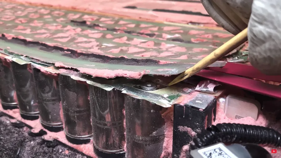
Reworkability is the ability to remove cured TIM cleanly from the module and reapply fresh material during module repair or end-of-life battery refurbishment. Cured silicone elastomer gap fillers peel cleanly from metal and PCB surfaces without adhesive residue. As EV battery packs become more valuable and second-life battery applications mature, reworkable TIM enables module-level repair rather than full pack replacement — real economic value that should be specified, not assumed.
The Decision Has Changed
TIM selection for EV battery modules used to happen after cell chemistry, after module architecture, after the cooling system. In next-generation pack development, it must happen concurrent with all three. The materials engineering decision affects thermal performance, reliability, and end-of-life value in ways that the commodity procurement approach — comparing material cost per unit area — fundamentally cannot capture.
Discuss Your Next-Generation Pack TIM Requirements
Our technical team works with EV battery module design teams on TIM selection, qualification planning, and process design — from initial grade screening through production qualification. Contact us early in the design cycle, not after the module architecture is fixed.