The Hidden Cost of Over-Specified Thermal Materials in Consumer Electronics
The TIM over-specification problem is less visible than under-specification — but it’s equally real. The most common TIM specification error in consumer electronics is not under-specifying thermal conductivity. It’s over-specifying it.
The POV
Over-specified TIM is not conservative engineering — it’s unverified engineering. If you can’t trace your TC requirement back to a specific thermal model output, your spec is a guess. The cost of that guess compounds at production volume — and the modulus consequence creates reliability risks that don’t appear in the BOM comparison.
How Over-Specification Happens — Two Mechanisms
Over-specification isn’t reckless — it’s usually methodical. Both mechanisms feel like prudent engineering at the time they happen. The problem is that neither of them is verified against the actual design requirement.
What Over-Specification Actually Costs
Two costs — material cost and modulus consequence. The material cost is visible in the BOM comparison. The modulus consequence is invisible until it shows up in reliability testing or early field returns.
Cost 1 — Material Cost: 40–80% Premium Nobody Approved
The cost difference between a 2.4 W/mK and a 6 W/mK gap filler can be 40–80% on a per-gram basis. For a consumer electronics product at production scale, this difference is not trivial.
At 50 million units per year with 0.5g TIM per unit, the material cost premium from a carry-over 6 W/mK spec vs. a fit-for-purpose 2.4 W/mK grade compounds into a significant annual line item — attributable entirely to a spec that nobody revisited. This is not a BOM optimization opportunity. It’s a specification error that was never caught.
Cost 2 — Modulus Consequence: The Reliability Risk Nobody Budgeted
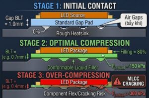
Higher-TC gap fillers have higher filler loading, which increases modulus. A 6 W/mK grade typically has significantly higher Shore E hardness than a 2.4 W/mK grade — which means higher compression stress on every component and PCB it contacts.
MLCC Cracking (0201, 0402)
Ceramic capacitors are sensitive to flexural stress. Excessive TIM compression force creates sustained mechanical load on MLCC case sizes — a known cracking failure mode that is difficult to attribute to TIM without detailed failure analysis
BGA Solder Joint Fatigue
Non-uniform compression across a BGA footprint creates shear stress that accumulates over thermal cycling — manifesting as early field returns or reliability test failures that trace back to mechanical loading, not solder quality
The trade-off nobody articulated: Using a harder TIM ‘for thermal margin’ trades mechanical safety margin on fragile components for thermal margin that wasn’t needed. The right TIM hardness is the minimum needed to achieve adequate pump-out resistance and vertical stability for the application — not the maximum available in a high-TC grade.
When Over-Specification Is the Right Call
To be clear: specifying above the thermal model’s minimum is sometimes appropriate. Three specific conditions justify it — each traceable to a real design constraint, not a vague preference for margin.
Low-Confidence Thermal Model
If you’re modeling a new form factor without heritage data, a higher-TC TIM may be the right insurance policy for the first generation — with a value-engineering exercise in generation 2 once you have real-world thermal data
Discontinuous Grade Availability
If your thermal model says 3.0 W/mK is sufficient but available grades are 2.4 W/mK and 5.1 W/mK, the 5.1 W/mK grade may be correct to avoid a custom qualification — as long as the modulus is acceptable for your component landscape
Multiple Thermal Scenarios
A device that operates in both standard and performance modes has a higher thermal peak than the average case model captures. Spec for the peak scenario — not the average. This is not over-specification; it’s correct specification for the actual operating envelope
The distinction between justified and unjustified over-specification is traceability. If you can point to a specific thermal model output, a specific operating scenario, or a specific grade availability constraint — the spec is justified. If the answer is “we carried it over from the previous product” or “we added margin” — it isn’t.
The Process That Prevents Over-Specification
Four process steps that catch over-specification before it becomes a production cost problem. Each step substitutes a traceable technical decision for an inherited or conservative assumption.
Specification Process — 4 Steps
Model at Actual Power Envelope
Run the thermal model at the actual power envelope — not a worst-case stack that accumulates 3–4× margin at each stage. Model at maximum sustained power, then add a single reasonable margin. Stacked margins are unverified engineering
Specify the Requirement — Then Select the Material
Specify the minimum TC, maximum hardness, and minimum TR that meet the design requirement — then select the material that meets this spec. Do not start with a material and verify it meets the spec. The order matters
Revisit Specs at Each Product Generation
Requirements change, materials improve, and the spec correct two years ago may not be optimal today. Build a TIM specification review into the product development checklist — not as a box to check, but as a genuine re-evaluation
Involve the TIM Supplier Early
A supplier who knows your thermal constraint can suggest the right grade — not just quote the grade you asked for. Early supplier involvement in the specification process is the fastest path to both the correct grade and the optimal price point
Frequently Asked Questions
TIM over-specification occurs when a material with TC, hardness, or specs above what the design actually requires is used — at higher cost and with unnecessary process trade-offs. It happens through two mechanisms: carry-over specs from a previous higher-power-density product that travel to a new product with lower requirements; or conservative margin stacking where 3–4 margins accumulate at each thermal model stage, resulting in a worst-case specification that doesn’t represent any realistic operating scenario.
The per-gram cost difference between a 2.4 W/mK and a 6 W/mK gap filler is typically 40–80%. At 50 million units per year with 0.5g TIM per unit, this premium compounds into a significant annual materials cost difference — attributable entirely to a specification that was never verified against the actual thermal model output. The cost is real but invisible, buried in the per-gram BOM line rather than visible as an ‘over-specification’ cost.
Yes. Higher-TC grades have higher filler loading and higher modulus. In designs with thin PCBs, fine-pitch BGAs, and 0201–0402 MLCCs, excessive TIM compression stress contributes to BGA solder joint fatigue and MLCC cracking under sustained compression load. These failure modes appear in reliability testing or early field returns and are difficult to attribute to TIM over-specification without detailed failure analysis — making them easy to misattribute to solder quality or component defects.
Three conditions justify it: (1) Low-confidence thermal model — new form factor without heritage data; higher TC is reasonable for generation 1 with a value-engineering review in generation 2; (2) Discontinuous grade availability — required TC falls between available grades and the next step up has acceptable modulus; (3) Multiple operating scenarios — specify for the peak power mode, not the average. In all three cases, the over-specification is traceable to a specific constraint. If it isn’t traceable, it isn’t justified.
Run the thermal model at the actual power envelope — not a stacked worst-case. Specify the minimum TC, maximum acceptable hardness, and minimum TR that meet the design requirement — then select the material. Not the other way around. Revisit the TIM spec at each product generation. Involve the TIM supplier early — they can suggest the right grade for your thermal constraint, not just quote the grade you asked for.
The right TIM hardness is the minimum needed to achieve adequate pump-out resistance and vertical stability for your specific application — not the maximum available in a high-TC grade. For most consumer electronics with controlled gap geometry and moderate thermal cycling, lower-hardness grades (Type E hardness 10–30) are sufficient and impose less mechanical load on stress-sensitive components. Higher hardness is only justified when pump-out resistance is demonstrated to be inadequate at lower hardness.
The Specification Principle
Specify the minimum TC, maximum hardness, and minimum TR that meet the design requirement — then select the material. If you can’t trace your TC requirement back to a specific thermal model output at a specific operating condition, your spec is a guess. The cost of that guess — both in material cost and in modulus-driven reliability risk — compounds at production volume in ways that aren’t visible until late in the product lifecycle.
Request a Thermal Specification Review for Your Application
Our technical team can review your current TIM specification against your thermal model and product requirements — identifying whether your TC requirement is correctly specified for your actual design constraints, or whether a fit-for-purpose grade would deliver equivalent thermal performance at lower cost and reduced modulus risk.