Voids and Cracks After Thermal Potting — Root Cause Analysis and Process Fixes
You open the housing after cure and find either bubbles trapped in the compound or cracks running through it. Both failures look similar at first glance — but they come from completely different causes and require completely different fixes.
The Single Most Important Distinction
Voids = process problem (air management during fill and mixing). Cracks = stress problem (material selection and housing geometry). Treating them the same way will not fix either one.
Two Failure Modes — Two Root Causes
Before attempting any fix, correctly identify which failure mode you are dealing with. Cross-section the part and examine the morphology — the shape, location, and pattern of the defect tells you which diagnosis applies.
Spherical or irregular air pockets — trapped during mixing or fill. Reduce effective thermal contact area, increasing thermal resistance at the component interface. Unacceptable in automotive and telecom reliability applications.
Air management
Fill rate & degassing
Mixer condition
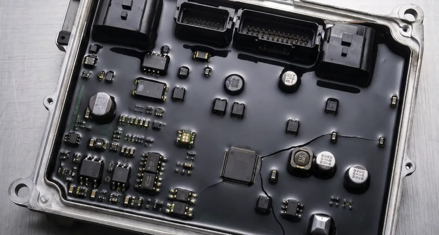
Linear fractures through cured compound — a stress failure, not a cure failure. The material cured correctly but internal stresses from shrinkage, thermal cycling, or geometric constraint exceeded the compound’s tensile strength or elongation limit.
Material selection
Housing geometry
CTE mismatch
Voiding — Root Causes and Process Fixes
Voids are air pockets. They form at three distinct points in the potting process — and identifying which point is generating the air determines which fix to apply.
Where Air Enters the System
During Mixing
Manual mixing whips air into the compound before it even reaches the housing. The faster and less controlled the mixing, the more air is incorporated
During Fill — Housing Geometry
Air trapped in housing cavities as compound flows in — particularly in complex geometries with narrow channels, undercuts, or tall vertical components that block the flow path
During Cure — Exotherm Degassing
Air or volatiles released from the compound during cure — driven by the exothermic reaction or residual solvent. Results in voids that form after fill, not during it
Mixer Turbulence
A partially blocked static mixer creates turbulent, irregular flow that whips air into the material during dispensing — independent of mixing or housing geometry
Process Fixes for Voiding
Vacuum Degassing Before Potting — Single Most Effective Step
Degas the mixed compound under vacuum for 5–10 minutes at <5 mbar before potting. This removes the majority of entrapped air regardless of how it was incorporated during mixing. For high-filler-loading compounds that resist degassing, extend the cycle to 15 minutes and watch for surface bubbling to stop — that is your indicator that degassing is complete.
Vacuum-Assisted Potting for Complex Housings
Pull vacuum on the assembly during fill — this forces the compound into all cavities and prevents air lock in complex geometries. Standard practice for telecom and EV power module applications where housing complexity makes gravity-fill unreliable. If your housing has undercuts, narrow channels, or blocked sight lines for fill inspection, vacuum-assisted potting is not optional — it is the only reliable method.
Control Fill Rate — Slow Initial Fill
Slow, controlled dispensing during the initial fill significantly reduces turbulence that entraps air. Fast fill into a deep housing almost always creates voids — the compound cannot displace air fast enough before it is trapped. Reduce your dispense rate for the first 20–30% of fill volume, then increase to production rate once a liquid head has been established above all cavity features.
Check and Replace the Static Mixer
A partially blocked static mixer generates turbulent, aerated flow before the compound reaches the housing. Replace the static mixer at the manufacturer’s recommended interval — not when you start seeing problems. By the time mixer failure is visible in the dispensed bead, you have already produced defective parts.
Cracking — Root Causes and Process Fixes
Cracks in cured potting compound are almost always a stress failure — not a cure failure. The material cured correctly. The internal stresses exceeded what the material can tolerate. Understanding where stresses originate determines which lever to pull.
Three Sources of Stress That Drive Cracking
Process Fixes for Cracking
Cross-Section the Part Before Changing Anything
Cross-section the failed part and examine crack morphology before making any process or material changes.
Cracks at Component Surface
CTE mismatch between component and compound — consider a more compliant (lower modulus) grade or a stress relief layer
Cracks at Housing Wall
CTE mismatch between housing and compound, or constraint from sharp internal geometry — review housing design and corner radii
Internal Cracks (No Wall Contact)
Cure shrinkage stress in a thick section — consider a lower-TC grade with higher elongation, or a staged cure profile
Consider a Lower-Modulus Grade
If you are running a high-TC potting compound (2.7–3.1 W/mK range) and cracking at corners or component bases, a lower-TC grade with higher elongation may be the correct trade-off — depending on your power density requirement. Calculate your maximum junction temperature at the lower TC value before switching. In many applications, a 1.5–2.0 W/mK grade with 150–200% elongation eliminates cracking with acceptable thermal penalty.
Ensure Complete Fill — Voids Are Crack Initiation Sites
Incomplete fill creates internal voids — and voids are preferential crack initiation sites under thermal cycling. The stress concentration around a void boundary is significantly higher than in fully filled material. If you are seeing cracks originating at locations away from walls or components, look for adjacent voids in the cross-section. Slow fill and vacuum-assisted potting address incomplete fill and reduce void-initiated cracking simultaneously.
Review the Cure Profile — Slow Cure Reduces Residual Stress
A fast, high-temperature cure generates higher residual stress than a slower cure — the compound transitions from liquid to solid more rapidly, and the thermal gradients during fast cure create non-uniform stress across the section. A room-temperature cure followed by a post-cure step allows the compound to develop crosslink density gradually with lower residual stress at the substrate interfaces. This is particularly effective for thick-section potting where temperature gradient through the depth during fast cure is significant.
Voids vs Cracks — Diagnostic and Fix Reference
| Dimension | Voiding | Cracking |
|---|---|---|
| Root cause category | Process — air management | Stress — material selection + geometry |
| Visual morphology | Spherical or irregular bubbles; may be visible on cut surface | Linear fractures; may follow component edges or housing walls |
| When it forms | During mixing or fill; sometimes during cure (exotherm) | During cure (shrinkage) or during thermal cycling (fatigue) |
| Primary thermal impact | Reduced thermal contact area → higher interface resistance | Loss of structural integrity; potential delamination at next cycle |
| Fix priority 1 | Vacuum degas compound before potting (5–10 min @ <5 mbar) | Cross-section and identify crack initiation site before changing anything |
| Fix priority 2 | Vacuum-assisted potting for complex housing geometries | Consider lower-modulus / higher-elongation grade |
| Fix priority 3 | Slow initial fill rate to prevent turbulence and air lock | Review housing geometry — eliminate sharp corners and abrupt thickness transitions |
| Fix priority 4 | Replace static mixer on schedule | Slow the cure profile — room temp cure + post-cure reduces residual stress |
| Material lever | None — this is a process issue | Lower TC grade with higher elongation may be the correct trade-off |
| Key diagnostic test | Cross-section and count voids by location (surface vs internal) | Cross-section and identify crack initiation point: component, wall, or internal |
Frequently Asked Questions
Voids form from air entrapment at three points: (1) air mixed into compound during the mixing step — especially with manual mixing; (2) air trapped in housing cavities during fill, particularly in complex geometries with narrow channels or undercuts; (3) air or volatiles released from the compound during cure due to exothermic reaction. The single most effective fix is vacuum degassing for 5–10 minutes at <5 mbar before potting.
Cracking is a stress failure — not a cure failure. The material cured correctly. Three root causes: (1) cure shrinkage stress in high-filler-loading compounds, where higher TC grades have higher modulus and lower elongation; (2) CTE mismatch between the potting compound and the housing or components, creating cyclic stress at every temperature swing; (3) stress concentration from sharp internal corners, tall unsupported components, or abrupt bondline thickness transitions.
Cross-section the part. Voids appear as spherical or irregular bubbles — isolated air pockets with no preferred direction. Cracks appear as linear fractures that follow stress concentrations: along component edges, at housing wall intersections, or through the thickest cross-section. Voids are a process failure (air management). Cracks are a stress failure (material selection and housing geometry). The fixes are entirely different — do not apply the same corrective action to both.
Vacuum degassing at <5 mbar for 5–10 minutes removes the majority of entrapped air from most compounds. For high-filler-loading grades, extend to 15 minutes and use the cessation of surface bubbling as your completion indicator. Note: degassing addresses air from mixing but does not prevent air entrapment from complex housing geometry during fill — that requires vacuum-assisted potting during the fill step itself.
It depends on whether your power density budget allows it. Lower-TC grades (1.5–2.0 W/mK) typically have higher elongation and lower modulus than high-TC grades (2.7–3.1 W/mK), which significantly reduces cracking susceptibility under thermal cycling. Before switching, calculate your maximum junction temperature at the lower TC value using your thermal model. In many applications, the reduction in cracking failure rate justifies the thermal trade-off — but this must be verified for your specific power density.
Yes — voids are preferential crack initiation sites. The stress concentration at a void boundary under thermal cycling is significantly higher than in fully filled material. An assembly that passes initial inspection with small internal voids may develop cracks initiating from those voids after repeated thermal cycles. This is why incomplete fill is a concurrent risk factor for both failure modes: slow fill and vacuum-assisted potting reduce void density and subsequent crack initiation risk simultaneously.
Bottom Line — Diagnosis Before Treatment
Cross-section the failed part first. Identify the failure mode — bubble or fracture — before applying any fix. Voids are an air management problem solved by degassing and fill process control. Cracks are a stress problem solved by material selection and housing geometry. Applying the wrong fix wastes time and does not address the root cause.