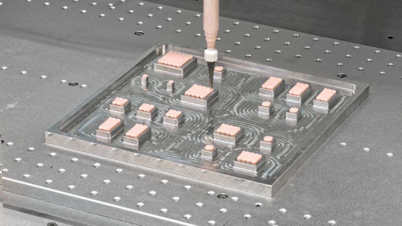
Dispensing Pressure, Nozzle Size, Speed — Tuning Your 2-Part Gap Filler System
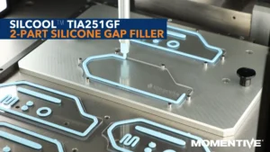
Silicone gap fillers don’t dispense like epoxies or solder paste. Their rheological behavior — the interplay of viscosity and thixotropy — means that getting consistent output requires understanding what you’re actually tuning, not just turning up the pressure.
If Dispensability Is the Issue, Suspect the Process — Not the Material
In the vast majority of gap filler dispensing problems, the root cause is a process variable — temperature, mixer condition, pressure, or nozzle — not a material defect. Verify these four in that order before concluding the material is out of spec.
The Physics Behind Gap Filler Dispensing: Viscosity vs. Thixotropy
Every gap filler formulation has two key rheological properties that govern dispensing behavior. Understanding how they interact is essential for systematic process tuning — because they can work against each other in a live dispensing system.
Resistance to flow. A high-viscosity material requires more force to move through a nozzle. Higher filler loading — needed for higher thermal conductivity — generally means higher viscosity. This is a static property that you tune with pressure and nozzle size.
Tuned via pressure
Temperature dependent
The tendency to thin under shear and then recover structure when shear stops. Allows the material to flow well during dispensing (shear-thinning) but hold its shape on the substrate afterward (shape retention) — enabling a non-slumping bead to hold position before assembly.
Shape retention after
Changes through a run
The interaction problem: A highly thixotropic material behaves differently at the start of a cycle (structure intact, higher apparent viscosity) versus mid-run (structure partially broken down, lower apparent viscosity). This is why process tuning is iterative — not a one-time setup — and why tuning done on the first cartridge of the day may not hold through the third.
Parameter-by-Parameter Tuning Guide
Four parameters control gap filler dispensing output. Tune them in this sequence — pressure first, because everything downstream depends on having correct flow rate established before optimizing geometry and timing.
Parameter 1 — Dispense Pressure
Start at the midpoint of your system’s pressure range and adjust from there. Do not start at the top of range — this is the most common mistake in initial setup and makes it impossible to identify the correct operating point systematically.
Pressure Too Low
Under-fill, inconsistent bead width, skip marks in the bead — material not moving through the nozzle at the required rate for your traverse speed
Pressure Too High
Over-fill, air introduction at the nozzle entry, and potential leakage past static mixer seals on 2-part systems — accelerated mixer wear and mix ratio drift
Calibration method: If your material TDS specifies dispensability in g/min at a reference pressure (e.g., 90 psi through a 2 mm nozzle), use this as your calibration point. Measure actual output rate at that pressure, then adjust to match your required flow rate for your specific nozzle and bead geometry.
Parameter 2 — Nozzle Size
Nozzle diameter determines both flow rate and bead geometry. The relationship is not linear — small changes in nozzle diameter create large changes in flow resistance (pressure drop scales with diameter to the fourth power in laminar flow).
Larger Nozzle
Lower pressure requirement for the same flow rate. Wider bead, lower placement precision. Better for flat, simple interface topographies and high-viscosity grades
Smaller Nozzle
Higher placement precision for complex 3D topographies. Requires higher pressure — which accelerates mixer wear on 2-part systems. More sensitive to viscosity variation from temperature
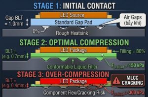
BLT verification: For gap fillers with minimum bond line thickness (BLT) specifications — such as 80 µm for TIA241GF or 150 µm for TIA251GF — nozzle size affects whether you are depositing the correct volume to achieve target BLT after compression. Always verify with a controlled BLT measurement during setup, not visual inspection alone. Visual inspection of bead width cannot predict post-compression BLT.
Parameter 3 — Dispense Speed (XY Traverse Rate)
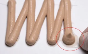
Dispense speed controls bead width and uniformity by setting the ratio of material output rate to stage movement rate. At constant pressure and nozzle size, faster traverse = narrower bead; slower traverse = wider bead. Both extremes create problems.
Too Fast
Thin, inconsistent bead with potential skip marks where the stage outpaced material flow — insufficient volume deposited, BLT will be below spec after compression
Too Slow
Over-deposition and potential for material to cure or gel in the nozzle between cycles — particularly relevant near pot life limits for 2-part systems with pot lives of 1–4 hours
Idle time management: For 2-part materials with pot lives of 1–4 hours, maximum idle time in the dispenser must be defined and enforced. Establish a maximum idle interval and program a short purge cycle if the system sits idle beyond that threshold — do not rely on operators to remember this manually.
Parameter 4 — Static Mixer Selection and Condition
The static mixer is the most frequently overlooked variable in gap filler process tuning. Mixer element count and geometry affect both mixing quality and system back pressure simultaneously — changing the mixer changes the effective operating point of all other parameters.
More Elements
Better mixing homogeneity and more complete A:B integration — but higher back pressure, requiring higher dispense pressure to maintain the same flow rate
High-Viscosity Grades
For grades at 10 W/mK and above, verify mixer selection against the material viscosity specification — not all static mixers are rated for high-viscosity silicone compounds
Replace on Schedule
A worn or partially blocked mixer creates turbulent flow, whips air into the material, and can cause mixing ratio drift — replace at the manufacturer’s interval, not when problems appear
Common Tuning Mistakes and How to Avoid Them
Most dispensing problems that appear to be material defects trace back to one of these four process mistakes. Each one is preventable with the right setup protocol.
Single-Variable Thinking
Adjusting only pressure when the actual problem is a multi-variable interaction — viscosity + temperature + mixer condition. If one parameter change doesn’t fix it, systematically check all four before concluding the material is bad
Ignoring Seasonal Temperature Variation
Tuning at ambient temperature without accounting for seasonal variation in your production space. Silicone viscosity changes measurably with temperature — a process tuned in summer may fail in winter in an unconditioned facility
Using Same Parameters Across Formulations
Applying the same dispense parameters to different gap filler grades without re-qualifying. Each formulation has unique rheology — even products with the same nominal TC from the same manufacturer can have significantly different viscosity and thixotropy profiles
Cold Cartridge from Storage
Not accounting for cartridge equilibration time. Material from cold storage (e.g., 5°C refrigerator) can be significantly more viscous than material at production room temperature — allow full equilibration before qualifying dispense parameters
Dispensing Problem Quick-Reference Table
Symptom-to-cause mapping for the most common dispensing issues with 2-part silicone gap fillers. For each symptom, the probable causes are listed in order of likelihood.
| Symptom | Probable Cause(s) | First Check |
|---|---|---|
| Thin, narrow bead with skip marks | Traverse speed too high; pressure too low | Reduce traverse speed, then increase pressure if needed |
| Over-wide bead, over-deposition | Traverse speed too low; pressure too high; nozzle too large | Increase traverse speed first |
| Inconsistent bead width run-to-run | Thixotropy variation through cycle; temperature change; cartridge not equilibrated | Verify cartridge temperature; add idle purge cycle |
| Air bubbles in dispensed bead | Worn or blocked static mixer; pressure too high; material not degassed | Inspect and replace static mixer |
| Material curing in nozzle between cycles | Idle time exceeds pot life limit; dispense speed too slow | Define and enforce maximum idle interval with purge cycle |
| BLT below spec after compression | Insufficient deposit volume; nozzle too small; incorrect BLT verification method | Measure BLT with gauge, not visual inspection |
| Material flows differently after lunch break | Cartridge cooled; room temperature dropped; thixotropic recovery after idle | Add purge cycle after any idle period >15 minutes |
| Mix ratio drift — partial cure observed | Worn pump valves; blocked outlet on one component; mixer back pressure too high | Weigh A and B outputs separately — verify within ±5% of target |
Frequently Asked Questions
The most common cause is thixotropic behavior — the material has a different apparent viscosity at the start of a cycle (structure intact) versus mid-run (structure partially broken down from shear). Other causes include temperature variation in the production space, cartridge equilibration issues if material came from cold storage, and thixotropic recovery during idle time between cycles. Add a purge cycle after any idle period exceeding 15 minutes to re-establish consistent flow conditions.
Start at the midpoint of your system’s pressure range and adjust from there. If your material TDS specifies dispensability in g/min at a reference pressure and nozzle size, use that as your calibration point — measure actual output rate at those conditions, then adjust to match your required flow rate for your specific nozzle and bead geometry. Starting at maximum pressure prevents systematic identification of the correct operating point.
Nozzle size affects deposited bead volume per unit length — which determines available material for achieving target BLT after compression. For gap fillers with minimum BLT specifications, always verify with a controlled BLT measurement during setup, not visual inspection. Bead width alone cannot predict post-compression BLT because the relationship also depends on bead volume, substrate area, and compression force simultaneously.
Replace at the manufacturer’s recommended interval — do not wait until you see problems. A worn mixer creates turbulent flow, introduces air, and can cause mix ratio drift. By the time failure is visible in the dispensed bead, you have already produced out-of-spec parts. For high-viscosity grades (10 W/mK and above), verify your mixer model is rated for high-viscosity silicone — not all standard static mixers are appropriate for these materials.
Two mechanisms cause post-idle variation: (1) thixotropic recovery — the material rebuilds its shear-thinned structure during idle, increasing apparent viscosity at the start of the next cycle; (2) partial cure — material in the nozzle or mixer begins crosslinking if idle time approaches the pot life limit. For 2-part systems with 1–4 hour pot lives, establish a maximum idle interval and program a short automatic purge cycle beyond that threshold.
Yes — significantly. Silicone viscosity decreases with increasing temperature, so a process tuned at 25°C will dispense differently at 18°C in an unconditioned facility in winter. Material from cold storage (5°C) can be substantially more viscous than fully equilibrated material. Always allow cartridges to equilibrate to production room temperature before qualifying parameters, and account for seasonal temperature variation when establishing your process window.
Tuning Order — When Something Isn’t Working
Verify in this sequence: (1) cartridge temperature — material equilibrated to room temp? (2) mixer condition — due for replacement? (3) pressure — calibrated against TDS dispensability spec? (4) nozzle — correct size for your viscosity grade and BLT requirement? Process tuning is iterative. Run the sequence before concluding the material is out of spec.