5G Base Stations Run Hotter Than 4G — What That Means for Thermal Interface Design
5G is not just 4G with a faster modem. The RF architecture of a 5G Massive MIMO Radio Unit is fundamentally different from a 4G eNodeB — and it creates a thermal management challenge that the 4G playbook doesn’t solve.
The POV
5G’s thermal challenge is not 4G’s with higher numbers. It’s a different problem — distributed heat sources, passive cooling requirements, variable-gap interfaces in sealed enclosures. The TIM solution that worked for 4G doesn’t solve 5G. The shift to liquid gap filler for RU PCB-to-chassis interfaces is driven by physics, not preference.
4G eNodeB vs. 5G Massive MIMO RU — Why the Thermal Problem Is Different
The architectural difference between 4G and 5G radio is not incremental — it is structural. The thermal consequences are equally fundamental, not merely quantitative.
The Thermal Path Problem — Why TIM Is the Remaining Lever
With fans ruled out and power density doubled, the only available thermal management lever in a 5G RU is the conductive path from PCB to enclosure exterior. Every resistance in that path matters — and TIM is the most designable of them.
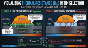
5G RU Conductive Thermal Path — Four Resistances in Series
| Resistance | Description | Designability |
|---|---|---|
| ① PCB copper spreading | Heat spreading through PCB copper layers from PAs to edge | Low — set by PCB stackup and layout |
| ② TIM resistance Most designable | PCB/component surface → cold plate or chassis back wall | High — TC grade, BLT, and dispensing process can all be changed |
| ③ Cold plate / chassis | Aluminum chassis thermal resistance through wall | Low — set by mechanical design |
| ④ Fin/surface to ambient | Convective resistance from enclosure exterior to ambient air | Low — set by fin geometry and enclosure design |
The TIM grade, BLT, and dispensing process can be changed independently — even in a late-stage design. This makes TIM one of the few remaining thermal levers once the mechanical design is set. For 5G RU design teams that inherited a 4G-era TIM specification, this is the optimization opportunity most likely to yield meaningful thermal improvement without mechanical redesign.
What Changed from 4G to 5G in TIM Requirements
Four specific TIM requirements have shifted materially between 4G and 5G radio unit design. Each shift is driven by a specific architectural or deployment requirement — not by a change in specification preference.
Higher TC — From 1.5–3 W/mK to 4–10 W/mK
4G RUs often used 1.5–3 W/mK gap pads or greases at the PCB-to-chassis interface. 5G RUs are specifying 4–10 W/mK liquid gap fillers for the same interface — driven by 2–4× higher power density with the same passive cooling constraint. The thermal budget doesn’t expand; the TIM TC has to.
At a typical 5G RU interface (30 cm², 25W, 0.3 mm BLT): 4.1 W/mK gap filler → ΔT = 0.61°C. A 1.5 W/mK 4G-era gap pad at 1 mm BLT → ΔT = 5.56°C. 9× higher thermal resistance with the 4G-era material at 5G power density.
Conformality Over Complex Topography — Not Possible with Fixed-Thickness Pads
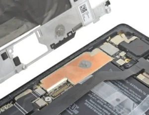
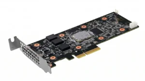
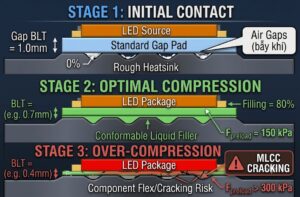
5G RF PCBs are more densely populated than 4G, with significant component height variation. A single liquid gap filler dispensed in situ handles all gap heights simultaneously. A gap pad requires multiple thickness SKUs to span the height variation — or creates void risk at short components where the pad bridges without contacting.
Gap variation across a populated 5G RF PCB: typically 0.5–2 mm across the same PCB assembly. A fixed-thickness pad at 1 mm nominal leaves air voids at 0.5 mm regions and over-stresses components at locations where gap closes below 1 mm.
Vibration Resistance — Pole-Mounted Outdoor RU Environments
5G RUs are often pole-mounted or tower-mounted in environments with sustained wind-induced vibration throughout their 10–15 year service life. Cured silicone elastomer gap fillers have inherent vibration damping — absorbing vibration energy rather than transmitting it to the PCB components beneath.
Gap pads under sustained vibration can experience micro-delamination at the interface — a contact loss that is invisible to remote monitoring until thermal performance degrades sufficiently to trigger an alarm. Cured silicone elastomers maintain conformal contact under vibration through elastic compliance.
Low Volatile Siloxane — Sealed Enclosures Concentrate Outgassing
5G outdoor RUs are hermetically sealed (IP66/IP67) against ingress. In a sealed enclosure, volatile cyclic siloxanes (D4–D10) that outgas from silicone-based TIM accumulate over time — and can contaminate optical transceivers and RF connector contacts inside the same sealed enclosure.
LV D4–D10 < 100 ppm is increasingly a hard requirement in 5G RU TIM specifications — not a preference. Unlike 4G enclosures with fan ventilation that dilutes outgassing, the 5G sealed passive-cooled enclosure concentrates any volatile output from the TIM over the unit’s lifetime.
The PCB-to-Chassis Interface in Massive MIMO — Where the Design Decision Matters Most
The highest-impact TIM decision in a 5G Massive MIMO RU is the interface between the populated RF PCB assembly and the chassis back wall. This is where the majority of power dissipated in the PA arrays is extracted to the exterior cooling path.
Variable Gap: 0.5–2 mm
Component height variation across the RF PCB creates a 0.5–2 mm gap range in the same assembly. Only a liquid gap filler that self-levels to actual gap depth can provide uniform thermal contact across this range without multiple pad thickness SKUs
Large Area: 200–400 cm²
Depending on antenna element count (32T32R to 64T64R and beyond), the PCB-to-chassis interface covers 200–400 cm² — any non-uniform thermal contact across this area creates cell-to-cell temperature variation in the PA array
High Thermal Sensitivity
1°C average temperature reduction at this interface corresponds directly to RF output power margin or extended PA lifetime. At network scale, sub-1°C thermal improvements translate to measurable network capacity and maintenance cost
Single Dispense Pass
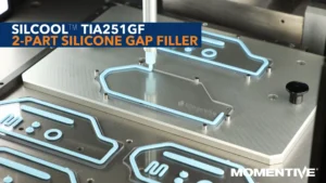
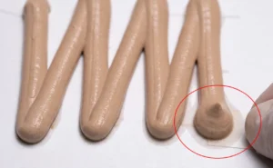
Liquid gap filler at 4–10 W/mK, dispensed by robot in a single pass, handles all three constraints simultaneously — variable gap, large area, and complex topography — without geometry-specific tooling or multiple SKUs
For 5G infrastructure design teams, this is the TIM interface worth re-evaluating even if the 4G approach was working — because the 5G power density makes the previous approach inadequate. Liquid gap filler at 4–10 W/mK is not an upgrade preference. It is the correct technical specification for the physical problem.
Recommended Gap Filler Grades for 5G RU PCB-to-Chassis Interfaces
Two grades cover the performance range from standard 5G mid-density RU to high power density Massive MIMO AAU — both meeting the low volatile, vibration resistance, and variable-gap conformality requirements of outdoor passive-cooled 5G RU deployment.
4.1 W/mK liquid dispensed silicone gap filler. Minimum BLT 120 µm. Handles 0.1–2 mm interface gaps. At 25W / 30 cm² / 300 µm BLT: ΔT = 0.61°C — vs. 5.56°C for a 1.5 W/mK 4G-era gap pad at 1 mm.
120 µm min BLT
0.1–2 mm gap range
Standard 5G RU
10.1 W/mK ultra-high TC silicone gap filler. Minimum BLT 280 µm. For high power density Massive MIMO AAU designs where the PA array power density pushes the limits of 4 W/mK grades and junction temperature budget is tight.
280 µm min BLT
High density AAU
64T64R+
| Parameter | TIA241GF — 4.1 W/mK | TIA2101GF — 10.1 W/mK | 4G-Era Gap Pad — 1.5 W/mK |
|---|---|---|---|
| TC (W/mK) | 4.1 | 10.1 Highest | 1.5 |
| Min BLT (µm) | 120 | 280 | ~500 |
| Gap range | 0.1–2 mm ✅ | 0.3–2 mm ✅ | Fixed thickness only ❌ |
| Variable gap conformality | ✅ Self-levels | ✅ Self-levels | ❌ Fixed thickness |
| Vibration resistance | ✅ Cured elastomer | ✅ Cured elastomer | ⚠️ Micro-delamination risk |
| Low LV siloxane | ✅ Verify TDS | ✅ Verify TDS | N/A |
| ΔT at 25W/30cm²/1mm BLT | 0.61°C (at 300µm) | 0.25°C (at 300µm) Lowest | 5.56°C ❌ |
| Best fit RU type | Standard 5G RU, mid-density macro | High density AAU, 64T64R+, tight thermal budget | 4G — not suitable for 5G power density |
Frequently Asked Questions
5G Massive MIMO RUs have 32–128 antenna elements each with its own PA and transceiver chain — creating power density 2–4× higher than comparable 4G radios across the RF PCB. Simultaneously, 5G outdoor RU enclosures require IP66/IP67 passive cooling — eliminating the active cooling fans that 4G equipment used. The thermal path from RF PCB to enclosure exterior must carry more heat with no active cooling assistance, making TIM TC the primary designable thermal variable.
Four 5G-specific requirements favor liquid gap filler: (1) Higher TC (4–10 W/mK vs 1.5–3 W/mK for 4G-era pads) to handle 2–4× higher power density; (2) Variable gap conformality — 0.5–2 mm gap variation across a 5G RF PCB that a single liquid gap filler handles in one pass; (3) Vibration resistance — cured elastomers maintain contact under sustained wind vibration where gap pads micro-delaminate; (4) Low volatile siloxane — sealed IP66/IP67 enclosures concentrate outgassing that 4G fan-cooled enclosures dispersed.
TIA241GF at 4.1 W/mK for standard 5G RU applications (0.1–2 mm gap range). TIA2101GF at 10.1 W/mK for high power density Massive MIMO AAU and 64T64R+ designs with tight junction temperature budgets. Both self-level to fill variable gaps in a single dispense pass and have published reliability data for thermal cycling and damp heat aging relevant to outdoor base station qualification.
5G outdoor RUs require IP66/IP67 hermetic sealing — eliminating the fan ventilation that diluted outgassing in 4G equipment. Volatile cyclic siloxanes (D4–D10) outgassing from silicone TIM accumulate over the unit’s 10–15 year service life and can contaminate optical transceivers and RF connector contacts inside the same sealed enclosure. LV D4–D10 < 100 ppm is increasingly a hard procurement requirement for 5G RU TIM. Verify current TDS for the specific grade before specifying into a sealed enclosure application.
5G RF PCBs with 32–128 antenna elements have component height variation creating 0.5–2 mm gap variation across the same PCB assembly. Liquid gap fillers self-level to fill whatever gap exists at each location — BLT is set by assembly closure pressure, not a fixed material thickness. A gap pad at one nominal thickness leaves air voids at thick-gap locations and over-stresses components at thin-gap locations across the same board.
At a typical 5G RU interface (30 cm², 25W): a 1.5 W/mK 4G-era pad at 1 mm gives ΔT ≈ 5.56°C. TIA241GF at 4.1 W/mK at 300 µm BLT gives ΔT ≈ 0.61°C — approximately 9× lower thermal resistance. TIA2101GF at 10.1 W/mK at 300 µm gives ≈ 0.25°C. At 5G power density in a passive-cooled enclosure, the 4G-era gap pad consumes most or all of the available thermal headroom between PA junction temperature and ambient limit.
The Design Decision
If you are specifying TIM for a 5G Massive MIMO RU PCB-to-chassis interface, the 4G-era TIM specification is not the right starting point. Start from 4 W/mK minimum for standard 5G RU — 10 W/mK for high-density AAU. Specify for variable gap (0.5–2 mm), vibration resistance, and LV siloxane compliance. Liquid gap filler dispensed in a single robot pass is the correct technical answer for all four requirements simultaneously.
Request Gap Filler Recommendations for Your 5G RU Application
Our technical team can recommend the right grade — TIA241GF or TIA2101GF — based on your RU power density, interface area, gap variation profile, and outdoor environmental qualification requirements including LV siloxane and thermal cycling specs.