Why the Next Generation of EV Battery Packs Will Be Won or Lost at the Cell Interface
The battery cell is getting better fast. The systems that manage it — including the thermal interface — are not keeping up at the same pace. That gap is where the next competitive advantage in EV battery design will be found.
The POV
The next competitive frontier in EV battery design is not cell chemistry — it’s the thermal, mechanical, and electrical management of cell-to-system interfaces. The TIM at the cell face is a precision engineering decision, not a procurement decision. Treat it accordingly.
Two Parallel Tracks — Both Make the Cell Interface More Critical
The EV battery cell is advancing on two simultaneous fronts. Both tracks generate more heat per unit volume of cell — and both make the thermal interface between the cell and the cooling system more critical, not less.
Silicon-anode cells targeting 350–400 Wh/kg at cell level — versus 250–270 Wh/kg for current-generation NMC. More joules in the same volume means more heat generated per unit volume during charge and discharge.
vs 250–270 Wh/kg today
+30–60% energy density
350kW+ charging rates for premium platforms, with mass-market vehicles targeting 200kW+ within three years. Higher charge rate means higher current, higher resistive heating, and faster heat generation across the pack.
200kW+ mass market
Localized tab heating
Both tracks move in the same direction: more heat per unit volume of cell, and more sensitivity to that heat. The temperature window within which lithium-ion cells degrade acceptably is roughly 25–40°C. The thermal interface at the cell face determines how much of that window is consumed by TIM resistance — or preserved for operating margin.
The Cell Interface Challenge at High Energy Density
Higher energy density cells are more thermally sensitive. The same temperature excursion that a first-generation cell tolerated gracefully may push a next-generation silicon-anode cell to the edge of its acceptable degradation window.
The 25–40°C Window
The temperature range within which lithium-ion cells degrade at acceptable rates. Outside this window — especially above 45°C — degradation accelerates via lithium plating, electrolyte decomposition, and SEI layer growth
How TIM Consumes the Window
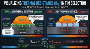
A thick TIM with high TR means the cell surface temperature is significantly higher than the cooling plate. Cooling plate at 25°C + 8°C TIM resistance = 33°C average cell surface, potentially 45°C during fast charging — at the edge of the window before aging
What Liquid Gap Filler Changes
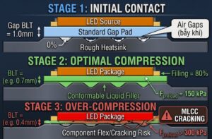
At 80 µm BLT, the TIM temperature rise is below 1°C. The cell surface and the cooling plate are effectively at the same temperature — the thermal management system can operate with much tighter control because the TIM is no longer a significant variable
The Margin You Can’t Afford to Waste
Manufacturing variation, aging, and edge-of-pack effects all consume thermal margin. A TIM that wastes 8°C of the 15°C available window leaves almost no margin for these real-world factors in a next-generation pack
| Scenario | Thick Gap Pad — 1 mm / 6 W/mK | Liquid Gap Filler — 80 µm BLT |
|---|---|---|
| Cooling plate temperature | 25°C | 25°C |
| TIM thermal resistance | 167 mm²K/W | ~30 mm²K/W |
| Cell surface temp (avg operation) | ~33°C | ~25.2°C Near cooling plate temp |
| Cell surface temp (fast charge) | ~45°C — edge of acceptable window | ~27°C — 18°C of margin preserved Safe |
| Margin for aging + variation | Near zero at fast charge | Substantial Preserved |
The Fast-Charging Geometry Problem — Why Cell Face Cooling Isn’t Enough
Fast charging at 350kW into a 100kWh pack means approximately 250A continuous current through the battery management system and into the cells. This heat is localized — appearing at cell tabs and interconnects, not uniformly across the cell face — creating a thermal management gap that cell face cooling alone cannot address.
Pack designs that address tab thermal management as part of the cell-level thermal interface — rather than relying entirely on cell face cooling — will have a structural advantage in fast-charge thermal performance. This is a design space that’s currently underexplored but will become increasingly important as charging rates scale beyond 200kW.
Reworkability as a Second-Life Enabler
Battery second-life economics are becoming real — a pack retaining 70–80% original capacity after 8–10 years of vehicle use is valuable for stationary storage. But only if it can be disassembled, tested, and reconfigured at reasonable cost. The TIM specification determines whether that’s possible.
Permanent Bond = Destructive Disassembly
A TIM that bonds permanently to cell and cooling plate makes module disassembly destructive — the cells cannot be separated from the thermal structure without damage that compromises their value for second-life redeployment
Reworkable Silicone = Clean Disassembly
A reworkable silicone elastomer gap filler peels cleanly from both cell and cooling plate surfaces — enabling module disassembly and cell replacement at a cost that makes second-life economics viable
Regulatory Pressure Is Building
As second-life battery markets develop and end-of-life battery regulations mature, reworkability may shift from a nice-to-have to a specification requirement driven by regulation — not engineering preference
Second-Life Value Preservation
A 70–80% capacity pack after 10 years represents real residual value for stationary storage — but that value is only realizable if the pack can be opened and the cells extracted without damage from the TIM
The Competitive Implication — Why 3°C Is a Business Argument
Battery chemistry is increasingly commoditized — the same cells are available to most OEMs within 6–12 months of a competitor’s design win. The systems that manage those cells are where differentiation persists. And it starts at the cell interface.
Better Cycle Life
3–5°C lower average cell temperature reduces lithium plating, electrolyte decomposition, and SEI layer growth rates — translating to measurably better cycle count retention across vehicle lifetime
Better Fast-Charge Performance
Lower cell temperature during fast charge enables the BMS to permit higher charge rates for longer — the thermal headroom preserved by a lower-TR TIM translates directly to charging speed that customers experience
Better Cold-Start Behavior
Lower thermal resistance means faster cell warm-up from the cooling plate during cold ambient — compliant elastomeric TIM maintains contact through the thermal expansion during warm-up that rigid pads may lose
Differentiation That Persists
Cell chemistry is available to all OEMs within months. Thermal management architecture — including the TIM specification — is proprietary engineering. The advantage compounds over the vehicle’s service life, not just at launch
Frequently Asked Questions
Battery cell chemistry is increasingly commoditized — the same cells are available to most OEMs within 6–12 months of a competitor’s design win. The systems that manage those cells — where differentiation persists — include thermal management and the cell-to-cooling-plate interface. An OEM managing cell temperature 3–5°C better than the field average sees measurably better cycle life, fast-charge performance, and cold-start behavior. Across a 200,000-mile vehicle lifetime, 3°C lower average cell temperature may represent 5–10% more retained capacity at end of life.
A 1 mm gap pad at 6 W/mK has TR ≈ 167 mm²K/W. With a cooling plate at 25°C, this adds 8°C+ to cell surface temperature during average operation — reaching ~45°C during fast charging. The acceptable degradation window for lithium-ion cells is roughly 25–40°C. A thick gap pad consumes most of this window in normal operation, leaving no margin for aging, manufacturing variation, or edge-of-pack effects in a next-generation high-density pack.
Fast charging at 350kW generates ~250A current through cell tabs, busbars, and interconnects. Resistive heating is localized at cell tab areas — not distributed across the cell face. A flat gap pad on the cell face provides a thermal path from the face but cannot address tab heating. Pack designs applying conformal gap filler around cell assemblies including tab areas create a continuous thermal path from tab to cooling structure — addressing the actual heat source location during fast charging.
A pack retaining 70–80% capacity after 8–10 years has real stationary storage value — but only if it can be disassembled at reasonable cost. A TIM that bonds permanently makes module disassembly destructive, destroying cell value. Reworkable silicone elastomer gap fillers peel cleanly from both cell and cooling plate surfaces, enabling module disassembly and cell replacement. As second-life battery markets develop, reworkability may shift from nice-to-have to a regulatory specification requirement.
Lithium-ion cells degrade at acceptable rates within roughly 25–40°C. Above 45°C, degradation accelerates via lithium plating, electrolyte decomposition, and SEI layer growth — reducing capacity and increasing thermal runaway risk. Higher energy density chemistries (silicon-anode cells, high-nickel NMC) are generally more thermally sensitive than first-generation chemistries, making the cell interface thermal resistance more critical in next-generation pack designs.
Across a 200,000-mile vehicle lifetime, 3°C lower average cell temperature may represent 5–10% more retained capacity at end of life — following Arrhenius degradation kinetics. Additionally, lower cell temperature during fast charging enables the BMS to permit higher charge rates for longer — translating to faster charging speeds customers experience directly. Both effects compound over the vehicle’s service life, creating advantages that persist beyond the initial competitive window for cell chemistry.
The Strategic Conclusion
Battery chemistry is converging. Thermal management is diverging. The OEM that manages cell temperature 3–5°C better will see measurably better cycle life, charging performance, and end-of-life value — and that advantage starts at the cell interface, with the TIM specification. Treat it as a precision engineering decision, not a procurement line item.
Discuss Cell-Level Thermal Interface Strategy for Your Next-Generation Pack
Our technical team works with EV battery module and pack design teams on cell-interface TIM strategy — from thermal model validation and grade selection through qualification planning for next-generation silicon-anode and high-nickel NMC platforms. Contact us at the architecture stage, not after the design is locked.