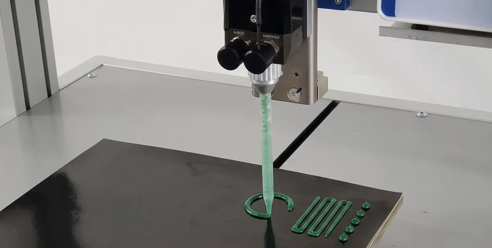
How to Design a Dispensing Process for 2-Part Silicone Gap Filler: Equipment, Nozzle, Pressure
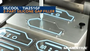
Switching from gap pads to liquid gap filler often stalls at the same point: the dispensing process. It looks complex from the outside, but the core decisions are fewer than you’d expect. Here’s the framework.
Process Design and Material Selection Must Happen in Parallel
A material that delivers 4.1 W/mK in a lab test but creates yield issues at production volumes due to process mismatch is not a viable solution. Characterize your equipment before qualifying your material — dispensing is a matching problem between material rheology and equipment capability.
The Second Qualification Axis Most Engineers Miss
Most engineers approach TIM selection by starting with thermal performance — TC, BLT, TR — and working backward to the material. That’s correct. But for 2-part dispensed gap fillers, there’s a second qualification axis that can override the thermal spec.
TC, BLT, TR — starts in the datasheet
Can your line apply this at the required rate and consistency?
Not sequentially — process mismatch can override the thermal spec
The Four Core Elements of a 2-Part Dispensing System
Every 2-part silicone gap filler dispensing system — from prototype to high-volume production — involves the same four components. Understand each one before selecting equipment or qualifying parameters.
Meter-Mix Dispenser — The Core Equipment Decision
For 2-part silicone gap fillers (A+B, 1:1 ratio by weight or volume), you need a meter-mix dispenser that delivers both components at the correct ratio. Two system types serve different production scales.
Start with a cartridge system for development and FAI. Simpler to set up, easier to characterize, and allows material switching without cleaning a bulk system. Move to bulk pump when production volume justifies the capital investment.
Static Mixer — Mixing Quality and Back Pressure
The static mixer is the component that determines mixing quality. For 1:1 ratio silicone gap fillers, a helical element mixer with minimum element count appropriate for the viscosity is required.
High-Viscosity Grades
Formulations such as TIA2101GF at 820/830 Pa·s per component require mixers rated for high-viscosity materials — verify with your dispenser vendor before qualifying the process
Element Count Trade-Off
Higher element count gives better mixing homogeneity but increases back pressure — raising the dispense pressure required to maintain the same flow rate at your nozzle
Replace on a Defined Schedule
Every shift or every N cartridges — whichever comes first. Do not wait for visible mixing issues. By the time mixer failure is visible, you have already produced out-of-spec parts
Nozzle Geometry — Flow Rate, Bead Shape, and BLT Control
Nozzle diameter controls both flow rate and bead geometry. Selection involves a fundamental trade-off between throughput and placement precision — match nozzle size to your interface geometry, not to a default.
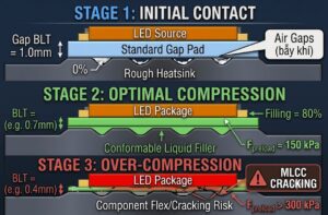
Critical BLT design note: The minimum BLT spec sets a physical floor on how much material can be compressed. For TIA241GF (minimum BLT 120 µm), over-depositing and then compressing will not get you below that floor — excess material flows laterally rather than compressing further. Design your dispensed volume and nozzle pass pattern to match your target bondline volume, not just surface coverage.
Process Parameters — The Three Variables You Tune in Sequence
Tune in this order — pressure first, because it establishes the flow rate baseline from which speed and tip gap are optimized.
① Pressure
Start at mid-range (typically 60–90 psi). Reference the dispensability data in TDS — TIA241GF is specified at 25 g/min per component at 90 psi through a 2 mm nozzle. Use this as your calibration point
② Speed (XY Traverse)
Set traverse speed to achieve target bead width and volume per unit length. Measure actual deposition weight on a scale at 3–5 test deposits before moving to part qualification — visual inspection alone is insufficient
③ Tip Gap
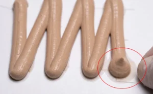
Distance from nozzle tip to substrate affects bead shape and spread. Start at 0.5–1× nozzle diameter for flat surfaces. Adjust based on observed bead shape — narrower bead needs larger tip gap; wider bead needs smaller
Assembly Window, Cure Schedule, and Cure Verification
For 2-part curing-type gap fillers, the assembly window — time from dispense to part closure — must be within the material’s pot life. Pot life constraints vary between grades and must be factored into production pacing during line design.
| Parameter | TIA241GF | TIA2101GF |
|---|---|---|
| Pot life @ 23°C | 2 hours More flexible | 1 hour — requires closer production pacing |
| Recommended cure (accelerated) | 70°C / 30 minutes | 70°C / 30 minutes |
| Room temperature cure option | 24 hours @ 23°C | 24 hours @ 23°C |
| Cure verification (hardness) | Type E hardness ≥ 45 | Verify against TDS specification |
| Viscosity per component | Refer to TDS | 820 / 830 Pa·s — requires high-viscosity mixer |
Cure verification proxy: If a laser flash or contact-resistance fixture is not available, use hardness as a cure completion proxy. Correct Type E hardness indicates complete cure — and a fully cured material will have achieved its rated thermal conductivity. Measure hardness at 3+ locations on a flat cured coupon before releasing your process for production.
Verification Checklist Before Production Release
Four verification steps must be completed and documented before releasing a new dispensing process for production. Each step catches a specific failure mode — do not substitute one for another.
① Verify Mix Ratio
Weigh A and B outputs separately over 10 dispense cycles at production parameters. Ratio must be within ±5% of spec. Off-ratio material will not cure correctly regardless of temperature or time
② Measure BLT
Apply material on a flat substrate, assemble with a parallel plate at your production clamp force, and measure actual bondline thickness after cure. Compare to your target BLT — not just the material’s minimum spec
③ Measure Thermal Resistance
Use laser flash or contact-resistance fixture if available. If not, use hardness as a cure proxy — correct hardness indicates complete cure and rated TC has been achieved
④ Run Aging Coupon
Cure a sample and measure hardness and TC at 0h, 500h @ 85°C, and 1000h @ 85°C if your application requires thermal aging data. Required for automotive and telecom qualification
Process Design Decision Reference
| Decision | Prototype / R&D / FAI | Production Volume |
|---|---|---|
| Dispenser type | Cartridge-based — low capital, fast material switching | Bulk pump system — higher throughput, better ratio control |
| Starting pressure | Mid-range (60–90 psi) — calibrate to TDS dispensability spec | Validated production parameter from FAI — document and lock |
| Nozzle size | 2 mm starting point for most gap filler grades | Optimized for interface geometry and target bead volume |
| Mixer replacement interval | Each session / each new cartridge during characterization | Every shift or every N cartridges — whichever comes first |
| Mix ratio verification | Every setup — weigh A+B separately over 10 cycles | At shift start and after any equipment change |
| BLT verification | Every process parameter change | Statistical sampling per production lot |
| Idle purge cycle | After any idle >15 minutes | Automated — after defined idle interval, before production restart |
| Cure method | RT cure (24h) or 70°C/30 min oven | 70°C/30 min oven — consistent, verifiable by hardness measurement |
Frequently Asked Questions
For prototyping and low-volume production, a cartridge-based meter-mix dispenser with static mixer attachment is the starting point — low capital cost and easy material switching. For production volumes above a few hundred units per day, a bulk pump system with separate A and B reservoirs is required. Both system types need a static mixer rated for your material’s viscosity grade and an XY dispensing stage or robot for bead pattern control.
Start at mid-range pressure (typically 60–90 psi) and calibrate to the dispensability data in the TDS. TIA241GF is specified at 25 g/min per component at 90 psi through a 2 mm nozzle — use this as your calibration point. Measure actual output rate at that condition, then adjust pressure and traverse speed to match your required deposition rate for your specific nozzle size and bead pattern.
Dispense Parts A and B separately into separate containers over 10 dispense cycles at production parameters, then weigh each. The ratio must be within ±5% of the target (1:1 by weight). Run this test at every equipment setup change and at the start of each production shift. Off-ratio material will not cure correctly regardless of temperature or bake time — this test must pass before running production parts.
TIA241GF has a pot life of 2 hours at 23°C. TIA2101GF has a pot life of 1 hour at 23°C. The assembly-to-cure window must be reliably within these limits under your worst-case production conditions. For TIA2101GF, production pacing must ensure no assembled board exceeds the 1-hour window before oven cure. Idle time limits and automatic purge cycles must be defined and enforced — not left to operator judgment.
Use Type E hardness as a cure proxy. Measure hardness on a flat cured coupon at 3+ locations — hardness reaching the TDS specification value (e.g., Type E ≥45 for TIA241GF) indicates complete cure. A fully cured material has achieved its rated thermal conductivity. This is accurate for production process control; laser flash or contact resistance measurement is required for formal thermal characterization during material qualification.
TIA241GF has a minimum BLT specification of 120 µm. This is a physical floor — over-depositing and applying more compression force will not produce a thinner bondline. Excess material flows laterally rather than compressing further. Design your dispensed volume to deliver the correct bondline volume for your target BLT. Verify actual BLT with a measurement after cure before releasing the process for production.
Key Principle: Dispensing Is a Matching Problem
Dispensing is a matching problem between material rheology and equipment capability. Most dispensability issues are process tuning problems, not material defects. Characterize your equipment before qualifying your material — verify temperature, mixer condition, pressure, and nozzle in that order before concluding the material is out of spec.