Thermal Potting for OBC / DC-DC Converters — What to Spec Before You Choose a Material
On-board chargers and DC-DC converters are among the most thermally demanding components in an EV powertrain. Selecting a thermal potting compound without a complete spec definition is one of the fastest ways to end up with a material that passes lab tests but fails in production or the field.
Define the Spec First — Then Select the Material
Six parameters must be defined before material selection begins: thermal conductivity, operating temperature / RTI, dielectric strength, modulus, viscosity, and LV siloxane content. Missing any one of these can result in a material that passes qualification but fails at the component or system level in service.
Why Thermal Potting Is the Right Approach for OBC / DC-DC Modules
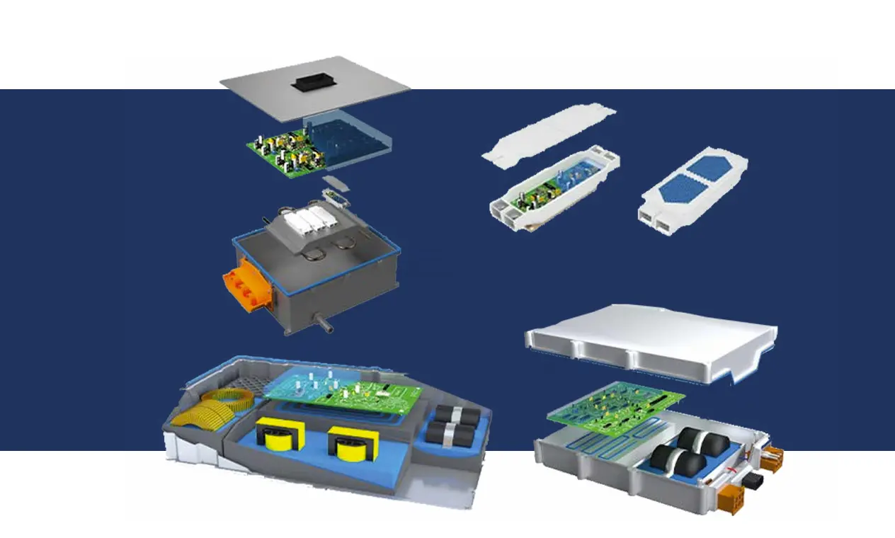
OBC and DC-DC modules pack high-density power electronics — MOSFETs, capacitors, transformers, inductors — into compact enclosures that must survive automotive temperature cycling, vibration, moisture ingress, and electrical isolation requirements simultaneously. No single material addresses all four except thermal potting compound.
Heat Transfer
Fills air gaps between components and enclosure, creating a conductive thermal path to the case that air cannot provide
Electrical Isolation
Electrically isolates high-voltage components from the housing — critical for 400V and 800V architecture OBC designs
Moisture Sealing
Seals the enclosure interior against humidity, condensation, and water ingress — essential for underhood automotive applications
Vibration Damping
Mechanically dampens vibration transmitted through the powertrain and road surface — protecting solder joints and component leads from fatigue failure
The Severity of the OBC / DC-DC Thermal Environment
The 6 Parameters to Specify Before Selecting a Potting Compound
Work through these six parameters in order. Each one constrains the next — defining thermal conductivity first establishes modulus trade-offs, which affects component stress, which affects the required hardness range, and so on.
Required Thermal Conductivity — Calculate From Your Model, Don’t Default to Highest
Run your thermal model first and determine what TC is actually needed to keep junction temperatures within budget. Do not default to the highest TC available — over-specifying TC adds cost and typically increases modulus, which raises mechanical stress on components during thermal cycling.
Typical OBC Range: 1.5–3.0 W/mK
Most OBC/DC-DC designs fall in this range. Higher TC is only justified if your thermal model shows the junction temperature cannot be kept within budget at 3.0 W/mK
TC vs. Modulus Trade-Off
Higher filler loading (needed for higher TC) increases modulus. Higher modulus increases stress on components and PCB during thermal cycling. This is the primary trade-off in OBC potting compound selection
Operating Temperature Range and RTI — The Long-Term Stability Indicator
For automotive applications, RTI (Relative Temperature Index) per UL 746B is the relevant long-term thermal stability indicator — not just the datasheet operating temperature range.
What RTI Means
A material rated RTI 150°C is certified for continuous operation at 150°C while maintaining specified electrical properties — not just short-term survival
When RTI Is Critical
Required if any part of your potted module reaches sustained temperatures above 105°C. Junction temperatures at power components in 800V OBCs frequently exceed this threshold
TIA216G Status
RTI 150°C planned — verify current certification status with your supplier before specifying into an application where sustained 150°C operation is required
Dielectric Strength and Volume Resistivity — Scaled to Architecture Voltage
Dielectric requirements scale with OBC architecture voltage. Specify the floor for your working voltage — then verify the material meets that floor after aging, not just at initial cure.
Critical: TIA216G has volume resistivity of 4 × 10¹⁴ Ω·cm at initial cure. Always verify that your required electrical isolation spec is met after 1000h aging at operating temperature — not just at t=0. Electrical properties of potting compounds can change with thermal aging, and the post-aging value is the relevant one for service life specification.
Modulus and Hardness — The Stress Trade-Off You Cannot Ignore
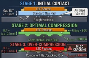
Higher-TC potting compounds tend to have higher filler loading, which increases modulus. Higher modulus means higher mechanical stress on components and PCB during thermal cycling — this is the fundamental trade-off that most OBC thermal spec documents underspecify.
Stress-Sensitive Components
Tall components, ceramic capacitors, transformer windings, and solder joints are at highest risk from excessive modulus. In 800V OBC designs, MLCC ceramic capacitors under the PCB are a common cracking failure mode from over-hard potting
TIA216G — Type E Hardness 40
Relatively soft for a thermal potting compound — good stress relief. Suitable for designs with stress-sensitive components. If your power density requires higher TC at the cost of higher hardness, validate with thermal cycling simulation on actual hardware before releasing to production
Viscosity and Potting Process Compatibility — Complex Geometries Need Low Viscosity
OBC housings often have complex internal geometries — capacitor clusters, transformer windings, PCB stacks. Low-viscosity potting compounds flow into tight spaces without voids. Higher-viscosity grades may require vacuum-assisted potting to prevent voiding in complex enclosures.
TIA216G Viscosity: 7.8 Pa·s
Low viscosity — flows into tight spaces without vacuum assistance in most OBC geometries. 1:1 mix ratio simplifies meter-mix dispenser setup and ratio verification
Pot Life vs. Fill Time
TIA216G cures in 30 min @ 70°C or 6 hours @ 23°C. Verify pot life against your production fill rate — if filling 30 seconds per module at a 2-hour pot life window, the math works
Vacuum Potting Decision
Required for geometries with narrow channels, undercuts, or tall component clusters that block gravity fill. Standard practice for telecom and automotive power module applications
Production pacing check: For slower lines or manual potting, verify that idle material in the dispenser does not begin crosslinking before the next module is filled. If your cycle time approaches 50% of pot life, add an automatic purge cycle or switch to a grade with longer pot life.
Low Volatile (LV) Content — D4–D10 Siloxanes — Increasingly Mandatory for Automotive
Automotive OEMs and Tier 1 suppliers increasingly specify maximum low-volatile siloxane content (D4–D10 cyclic siloxanes) in materials used inside vehicle cabins — including OBC and DC-DC converter enclosures where off-gassing could reach climate control intake systems.
Why LV Content Matters
D4–D10 siloxanes can contaminate automotive climate control sensors and degrade HVAC component performance over vehicle lifetime. Increasingly prohibited by OEM material approval standards
Typical OEM Requirements
LV D4–D10 < 100 ppm is the general floor. Some Tier 1 and OEM procurement specifications now require < 50 ppm for interior components. Verify TIA216G current TDS — LV content is grade-dependent and may vary by lot
OBC Thermal Potting Specification Matrix — TIA216G vs Typical Requirements
Use this matrix as a starting point for your material qualification spec sheet. Adjust requirement floors based on your architecture voltage, junction temperature budget, and OEM material standard.
| Parameter | Typical OBC Requirement | TIA216G Value |
|---|---|---|
| Thermal conductivity | 1.5–3.0 W/mK | 1.6 W/mK Within range |
| Dielectric strength | > 15 kV/mm | 20 kV/mm 33% margin |
| Volume resistivity | > 10¹² Ω·cm | 4 × 10¹⁴ Ω·cm 100× above floor |
| Hardness (Type E) | 20–50 (stress relief) | 40 Within range |
| Viscosity | < 20 Pa·s (complex fill) | 7.8 Pa·s Low viscosity |
| Mix ratio | 1:1 preferred (meter-mix simplicity) | 1:1 by weight/volume |
| Operating temp (RTI) | > 125°C | 150°C (planned) — verify certification status |
| Cure schedule | Heat-accelerated preferred | 30 min @ 70°C / 6h @ 23°C |
| LV siloxanes D4–D10 | < 100 ppm (some < 50 ppm) | Verify current TDS — grade-dependent |
| Reworkable | Preferred for repair/refurbishment | ✅ Yes — silicone elastomer |
Frequently Asked Questions
Calculate from your thermal model first — do not default to the highest TC available. Most OBC and DC-DC designs need 1.5–3.0 W/mK. TIA216G at 1.6 W/mK covers most mid-density OBC designs. Over-specifying TC adds cost and typically increases modulus, which raises mechanical stress on components during thermal cycling — a reliability risk for ceramic capacitors and solder joints in 2,000+ cycle automotive applications.
For 400V architecture: dielectric strength > 15 kV/mm and volume resistivity > 10¹² Ω·cm are standard floors. TIA216G provides 20 kV/mm and 4 × 10¹⁴ Ω·cm at initial cure. For 800V architecture, working voltage requirements drive minimum potting depth calculations — verify against IEC 60664-1 or your OEM isolation test standard. Always verify electrical properties meet your spec after 1000h aging — not just at t=0.
RTI (Relative Temperature Index) per UL 746B certifies continuous operation at a rated temperature while maintaining specified electrical properties. An operating temperature range on a TDS is not equivalent to RTI certification. RTI 150°C is critical if any part of your potted OBC module reaches sustained temperatures above 105°C — which is common at power component junction locations in high-power-density 800V designs. TIA216G RTI 150°C is planned — verify current certification status before specifying.
Higher-TC compounds use higher filler loading, which increases elastic modulus. During -40°C to +85°C thermal cycling (2,000+ cycles over vehicle service life), a high-modulus compound generates larger mechanical stress due to CTE mismatch. For stress-sensitive components — ceramic capacitors, transformer windings, solder joints — excessive modulus drives cracking failure. Specify hardness range alongside TC in your potting spec, and validate with thermal cycling simulation on actual hardware if modulus concerns exist. TIA216G Type E hardness of 40 is soft for a thermal potting compound — providing good stress relief at 1.6 W/mK.
LV (low volatile) siloxane content refers to D4–D10 cyclic siloxanes that can outgas from silicone-based potting compounds during service. In automotive applications, these volatiles can contaminate climate control sensors and degrade HVAC performance. Automotive OEMs and Tier 1 suppliers increasingly specify maximum LV D4–D10 content — typically < 100 ppm as a general floor, with some procurement standards now requiring < 50 ppm for underhood and interior components. Verify TIA216G current TDS — LV content is grade-dependent.
TIA216G viscosity of 7.8 Pa·s and 1:1 mix ratio allow gravity fill in most OBC geometries without vacuum. For complex housings with narrow channels, tall component clusters, or undercuts that block gravity fill, vacuum-assisted potting is recommended to prevent voiding. Vacuum potting is standard practice for automotive power module applications — if your housing has complex internal geometry, plan for it from the start.
Spec First, Then Select
Define all six parameters before requesting samples or quotations: (1) TC from thermal model → (2) RTI for sustained temperature → (3) dielectric strength post-aging → (4) hardness for stress relief → (5) viscosity for fill complexity → (6) LV content for OEM compliance. A material that passes on four of six cannot be qualified — all six must be met simultaneously.